

 English
 русский
 Deutsch
 Türk
 中文简体
High-Pressure Reinforced L-Type Seal: Engineering Guide for Gas Spring Dampers
High-Pressure Reinforced L-Type Seal: Engineering Guide for Gas Spring Dampers
High-Pressure Reinforced L-Type Seal: Engineering Guide for Gas Spring Dampers
High-Pressure Reinforced L-Type Seal: Engineering Guide for Gas Spring Dampers
High-Pressure Reinforced L-Type Seal: Engineering Guide for Gas Spring Dampers
High-Pressure Reinforced L-Type Seal: Engineering Guide for Gas Spring Dampers
High-Pressure Reinforced L-Type Seal: Engineering Guide for Gas Spring Dampers
High-Pressure Reinforced L-Type Seal: Engineering Guide for Gas Spring Dampers
High-Pressure Reinforced L-Type Seal: Engineering Guide for Gas Spring Dampers
High-Pressure Reinforced L-Type Seal: Engineering Guide for Gas Spring Dampers
High-Pressure Reinforced L-Type Seal: Engineering Guide for Gas Spring Dampers
High-Pressure Reinforced L-Type Seal: Engineering Guide for Gas Spring Dampers
High-Pressure Reinforced L-Type Seal: Engineering Guide for Gas Spring Dampers
High-Pressure Reinforced L-Type Seal: Engineering Guide for Gas Spring Dampers
High-Pressure Reinforced L-Type Seal: Engineering Guide for Gas Spring Dampers
High-Pressure Reinforced L-Type Seal: Engineering Guide for Gas Spring Dampers

Industry news
Home / News / Industry news / High-Pressure Reinforced L-Type Seal: Engineering Guide for Gas Spring Dampers
NEW Category
Contact us
High-Pressure Reinforced L-Type Seal: Engineering Guide for Gas Spring Dampers
Content
- 1 What Is a High-Pressure Reinforced L-Type Seal?
- 2 Core Design Features of the High-Pressure Reinforced L-Type Seal
- 3 Performance Comparison: Reinforced L-Type vs Y-Type vs O-Ring
- 4 How to Select the Right Seal for Gas Springs and Dampers
- 5 Common Failure Modes and Preventive Measures
- 6 Installation and Surface Preparation Guidelines
- 7 Frequently Asked Questions
A gas spring that runs at 12 MPa with a 1.5 mm radial gap will destroy an unreinforced elastomer lip seal in a matter of hours. This failure pattern is familiar to anyone who specifies seals for gas springs and dampers. The high-pressure reinforced L-type seal was designed specifically for this condition: it combines the axial lip action of an L-profile with a rigid backing insert that stops material flow into the clearance gap.
JNS Sealing Technology supplies this seal family for gas spring and damper manufacturers, with the reinforced L-type profile engineered for extreme-duty cycles. The lifespan of a gas spring often hinges on the seal's ability to hold high pressure across millions of strokes.
12 MPa
Peak pressure that triggers the need for a reinforced insert instead of a standard lip seal
What Is a High-Pressure Reinforced L-Type Seal?
A high-pressure reinforced L-type seal is a pressure-energized sealing component with an L-shaped cross-section, typically 8 to 10 mm tall, in which a rigid reinforcement insert supports the sealing lip to prevent extrusion under high pressure.
The L-profile consists of one flat contact surface and one flexible lip. When differential pressure is applied, the lip is pressed against the running surface, producing a sealing force that rises with pressure. The reinforcement element, either metal or high-strength composite, supports the lip from behind and resists the pressure gradient that would otherwise force elastomer material into the joint gap.
This changes the performance ceiling significantly. A standard L-type profile without reinforcement struggles above 6 MPa. The reinforced version reaches 10 to 15 MPa in gas spring duty cycles. JNS Sealing Technology classifies its reinforced L-type seal under the high-pressure product category and provides a detailed material comparison guide for NBR, HNBR, and FPM compound selection.
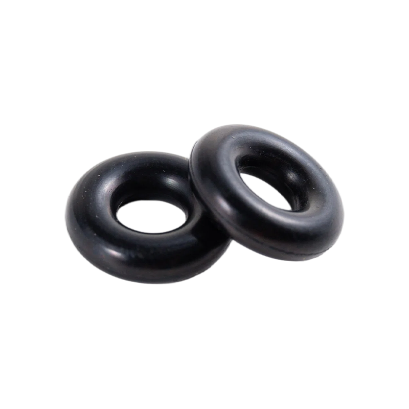
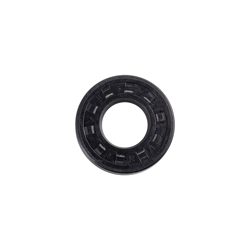 Reinforced L-Type Seal for High-Pressure Gas SpringsThis reinforced L-type seal withstands pressure shocks up to 1800N, featuring anti-extrusion design and thickened lips for heavy-duty applications. Proper elastomer selection is critical for achieving rated performance in gas spring duty cycles.View Product →
Core Design Features of the High-Pressure Reinforced L-Type Seal
Three variables determine the pressure rating and service life of the reinforced L-type seal: seal diameter, reinforcement geometry, and elastomer compound. Get these wrong and the design will fail before reaching the rated load.
Reinforcement Geometry
The insert sits at the base of the lip at 20 to 30 degrees to the piston axis. This angled placement distributes the radial load along the lip base and prevents lip inversion during pressure spikes. Metal inserts deliver the highest stiffness and suit heavy-duty gas springs. Composite inserts provide better corrosion resistance, lower weight, and quieter operation. Both options are available from JNS Sealing Technology.
Elastomer Compound
The working lip runs 50 to 70 Shore A for low friction and conformability. The body behind the reinforcement runs 85 to 95 Shore A for dimensional stability. This dual-durometer structure is the defining distinction of a reinforced L-type seal compared with a one-piece standard lip seal.
For high-temperature gas spring and damper service, HNBR and FPM are the most common compounds. HNBR withstands compressor oils and high temperatures up to 150 degrees Celsius while maintaining low compression set. FPM is better for high-temperature chemical exposure but has lower resistance to certain hydraulic fluids. JNS Sealing Technology validates each compound through its quality control process.
50-70 Shore A
Lip hardness range for low-friction, noise-free sealing in gas spring service
Performance Comparison: Reinforced L-Type vs Y-Type vs O-Ring
The choice between these three profiles depends on pressure, motion type, and available space. The reinforced L-type seal wins in high-pressure reciprocating service where extrusion resistance is the limiting factor.
10-15 MPa
Reinforced L-Type
8-10 MPa
Standard Y-Type
5-8 MPa
O-Ring
Gas springs differ from hydraulic cylinders in one critical way: the gas is compressible. This creates a nonlinear pressure curve during the stroke. A seal that works at the beginning of the stroke may be overloaded at the end. The reinforced L-type seal handles this dynamic range because the insert angle and reinforcement stiffness maintain a consistent radial load as pressure builds.
| Characteristic | Reinforced L-Type | Standard Y-Type | O-Ring |
| Peak pressure | 10-15 MPa | 8-10 MPa | 5-8 MPa |
| Extrusion resistance | High | Medium | Low |
| Sealing force | Pressure-activated | Pressure-activated | Compression |
| Primary failure mode | Reinforcement fatigue | Lip inversion | Extrusion |
| Typical application | Gas springs, dampers | Hydraulic cylinders | Static and dynamic sealing |
How to Select the Right Seal for Gas Springs and Dampers
Selection follows a five-step sequence. Skipping any step leads to premature failure or unnecessary cost.
- Define peak pressure. Capture the maximum pressure during the full service cycle, including pressure spikes, not just the nominal operating value. Size the reinforcement insert to sustain 1.3 times this peak without permanent deformation.
- Measure the radial gap. The gap between housing and piston determines the extrusion gap the seal must overcome. If the product experiences side load, measure the gap at the loaded condition.
- Select the reinforcement type. Metal inserts for maximum stiffness. Composite inserts for corrosion resistance and weight reduction.
- Choose the compound. Match the elastomer to the media, temperature range, and required compression set. HNBR for oil service up to 150 degrees Celsius. FPM for aggressive chemicals at higher temperature.
- Validate on a test stand. Run the seal through the expected duty cycle and inspect for extrusion, wear, or leakage before approving the design.
For gas springs, the most common cause of seal failure is not the pressure itself but the radial gap that opens under side load. Always measure the gap at the loaded condition, not the unloaded condition.
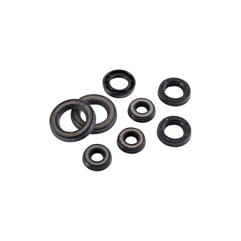
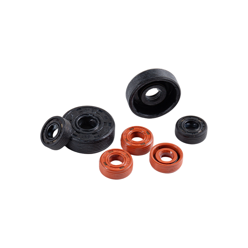 Balanced Damping Seal for 13mm Piston SystemsEngineered for 13mm OD piston systems, this seal has a 4.5mm height for broader contact, ensuring consistent damping force and preventing micro-leakage. Enhanced lateral load capacity addresses side-load induced gap failures.View Product →
Common Failure Modes and Preventive Measures
Four failure modes account for most reinforced L-type seal replacements in gas spring service. Identifying the root cause early prevents cascading damage to the rod, housing, and surrounding components.
- Extrusion. Material squeezes into the clearance gap under pressure. Prevention: select reinforcement rated for the gap and pressure, and tighten the housing tolerance.
- Lip wear. Caused by high friction, side load, or particle contamination. Prevention: use the lower Shore A lip compound and install rod wipers to keep the counter surface clean.
- Lip inversion. The lip folds backward under friction or pressure surge. Prevention: choose a reinforcement insert with the correct angle and keep the friction coefficient low through proper surface finish and lubrication.
- Compression set. Loss of elastic recovery after prolonged temperature exposure. Prevention: select HNBR or FPM compounds with compression set below 25 percent at 150 degrees Celsius.
A practical inspection schedule extends service life. Check the seal lip for hardening each quarter, measure the groove gap with a feeler gauge, and monitor for external leakage. In high-frequency gas springs, inspect the reinforcement insert for fatigue cracks at the bend radius every six months.
Typical failure rate by root cause
Installation and Surface Preparation Guidelines
The best seal design fails with poor installation. Surface finish, lead-in chamfers, and lubrication decide whether the seal survives its first cycle.
The counter surface should follow a Ra 0.4 to 0.8 micrometer finish. Surface defects above Ra 0.8 micrometers act as grind marks that abrade the lip during reciprocating motion. If the counter surface is plated or hardened, confirm the coating is free of micro-cracking. The reinforcement insert must not contact the mating surface directly, as this causes premature wear and scoring.
Lubricate the seal with the system fluid before installation, and use a lead-in chamfer of at least 15 degrees on the piston and housing edges. Sharp edges can cut the lip during installation and cause immediate leakage. A properly prepared surface combined with correct lubrication typically raises seal life by 30 to 40 percent in gas spring service.
JNS Sealing Technology offers the reinforced L-type in multiple size classes, and its factory overview details the production and inspection capacity available for custom dimensions.
Frequently Asked Questions
What is the maximum pressure for a reinforced L-type seal?
The reinforced L-type seal handles peak pressures from 10 to 15 MPa in gas spring service, depending on radial gap, reinforcement geometry, and compound selection. Standard unreinforced L-type seals top out around 6 to 8 MPa.
How does the reinforced L-type seal differ from a standard L-type seal?
The reinforcement insert is the defining difference. A standard L-type seal uses only elastomer material, which squeezes into the clearance gap at high pressure. The reinforced version has a metal or composite insert that supports the lip, preventing extrusion and enabling 10 to 15 MPa operation.
When should I choose a Y-type seal instead of a reinforced L-type seal?
Choose a Y-type seal when the installation space is tight and pressure stays below 10 MPa. The Y-type profile provides higher radial load capacity in a compact axial space, while the reinforced L-type is better for larger gas springs requiring long service life at extreme pressure.
What materials are best for high-temperature gas springs?
HNBR and FPM are the recommended materials. HNBR performs well up to 150 degrees Celsius in compressor oils with low compression set. FPM handles higher temperatures but has lower resistance to some hydraulic media. Match the compound to the specific fluid and temperature profile.
PREV:7.3mm Pneumatic-Grade Seal: Specs, Materials and Selection Guide for Engineers
NEXT:Rubber Ring Selection Guide: Materials, Sizes, and Standards for Sealing Engineers
NEXT:Rubber Ring Selection Guide: Materials, Sizes, and Standards for Sealing Engineers




Want to know more
about us?
about us?

Precision sealing for gas springs and dampers. Durable, wear-resistant, and built for long-life performance in demanding applications.
Product Categories
Quick Links
Contact Us
-
Email: jns@jnsseals.cn

-
Manager Gong: +86-18563770820

-
Manager Wang: +8615357558902
-
No. 5, Meilin Avenue, Meilin Industrial Development Zone, Ningguo City, Anhui Province, China

