

 English
 русский
 Deutsch
 Türk
Türk 中文简体
中文简体
O-Shaped Oil Seal Ring: Technical Guide for Industrial Sealing Applications
O-Shaped Oil Seal Ring: Technical Guide for Industrial Sealing Applications
O-Shaped Oil Seal Ring: Technical Guide for Industrial Sealing Applications
O-Shaped Oil Seal Ring: Technical Guide for Industrial Sealing Applications
O-Shaped Oil Seal Ring: Technical Guide for Industrial Sealing Applications
O-Shaped Oil Seal Ring: Technical Guide for Industrial Sealing Applications
O-Shaped Oil Seal Ring: Technical Guide for Industrial Sealing Applications
O-Shaped Oil Seal Ring: Technical Guide for Industrial Sealing Applications
O-Shaped Oil Seal Ring: Technical Guide for Industrial Sealing Applications
O-Shaped Oil Seal Ring: Technical Guide for Industrial Sealing Applications
O-Shaped Oil Seal Ring: Technical Guide for Industrial Sealing Applications
O-Shaped Oil Seal Ring: Technical Guide for Industrial Sealing Applications
O-Shaped Oil Seal Ring: Technical Guide for Industrial Sealing Applications
O-Shaped Oil Seal Ring: Technical Guide for Industrial Sealing Applications
O-Shaped Oil Seal Ring: Technical Guide for Industrial Sealing Applications
O-Shaped Oil Seal Ring: Technical Guide for Industrial Sealing Applications

Industry news
Home / News / Industry news / O-Shaped Oil Seal Ring: Technical Guide for Industrial Sealing Applications
NEW Category
Contact us
O-Shaped Oil Seal Ring: Technical Guide for Industrial Sealing Applications
Content
- 1 Understanding the O-Shaped Oil Seal Ring
- 2 Technical Specifications and Performance Factors
- 3 Application Scenarios and Industry Use
- 4 Comparison with Alternative Sealing Solutions
- 5 Selection Considerations and Purchasing Factors
- 6 Installation, Operation, and Maintenance
- 7 Common Mistakes and Overlooked Considerations
- 8 Industry Trends and Future Outlook
- 9 Conclusion
- 10 Frequently Asked Questions
- 10.1 What is the primary sealing mechanism of an O-shaped oil seal ring?
- 10.2 How do I select the correct elastomer material for my application?
- 10.3 What compression should be applied to an O-ring during installation?
- 10.4 What causes O-rings to fail prematurely?
- 10.5 Can O-rings be used in high-pressure applications?
- 10.6 What is the difference between static and dynamic O-ring applications?
- 10.7 What surface finish is required for O-ring sealing surfaces?
- 10.8 How should O-rings be stored to maximize shelf life?
The O-shaped oil seal ring, commonly referred to as an O-ring, represents one of the most fundamental yet critical components in fluid power systems and mechanical sealing applications. This circular elastomeric seal with a round cross-section functions by creating a leak-proof barrier between mating surfaces, preventing the escape of fluids or gases while excluding contaminants from entering the system. Despite its simple geometry, this sealing solution underpins the reliability of hydraulic cylinders, pneumatic systems, automotive assemblies, and industrial processing equipment across virtually every manufacturing sector.
Understanding the O-Shaped Oil Seal Ring
Definition and Basic Configuration
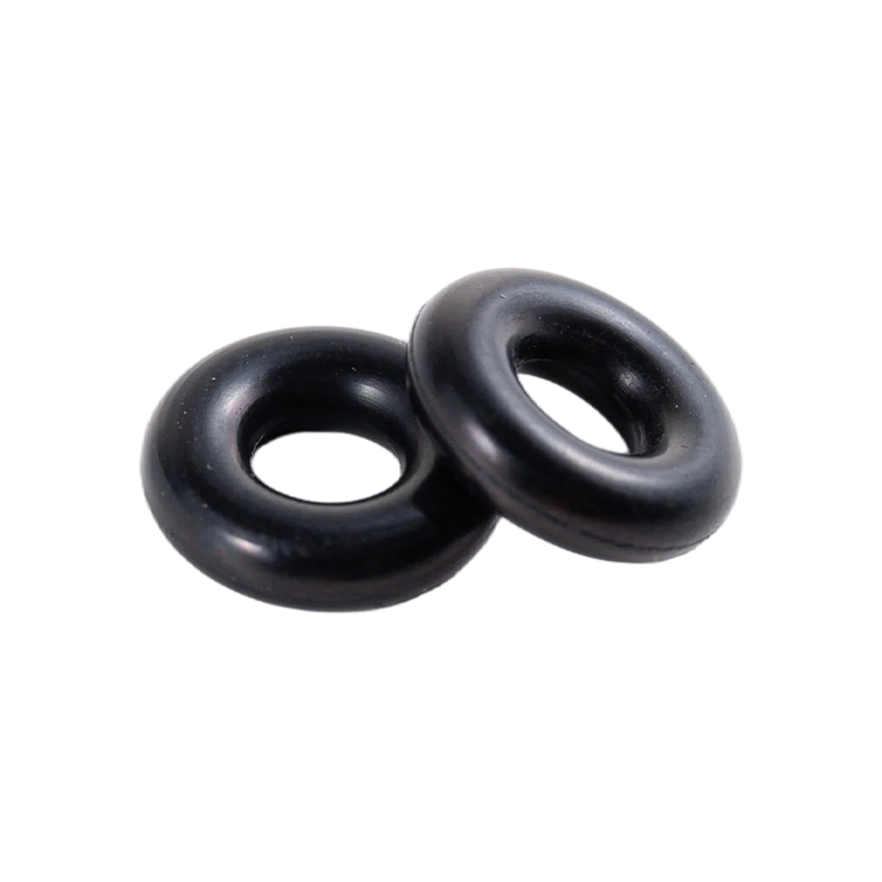
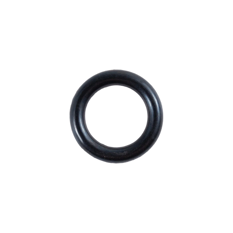
An O-shaped oil seal ring is a torus-shaped elastomeric sealing element designed to be compressed between two or more mating surfaces. The seal derives its name from its characteristic circular shape, which allows it to fit into a machined groove or gland and create a positive seal through radial or axial compression. The round cross-section geometry provides the seal with the ability to deform under pressure while maintaining the elastic recovery necessary to sustain sealing force over time.
The fundamental principle governing O-ring sealing relies on the elastomer's ability to store energy when compressed. This stored energy creates contact pressure against the mating surfaces, effectively blocking fluid passage. When properly specified and installed, an O-shaped oil seal ring can maintain its sealing function across a wide range of operating pressures, temperatures, and media types.
Working Principle and Sealing Mechanism
The sealing mechanism of an O-shaped oil seal ring operates on the principle of controlled deformation. When installed in a gland and subjected to system pressure, the seal undergoes compression that forces the elastomer against the groove walls and mating surfaces. The initial compression, typically ranging from 10% to 40% of the cross-sectional diameter for static applications, creates the sealing force necessary to prevent leakage.
System pressure serves to enhance the sealing effect by forcing the O-ring against the lower-pressure side of the gland. This self-energizing characteristic means that as system pressure increases, the sealing force also increases, improving the seal's effectiveness. In dynamic applications, where relative motion occurs between sealing surfaces, the O-ring must maintain contact pressure while accommodating movement without excessive wear or rolling.
Technical Specifications and Performance Factors
Dimensional Standards and Tolerances
O-shaped oil seal rings are manufactured according to established international standards that define both nominal sizes and tolerance limits. The AS568 standard provides a comprehensive sizing system for inch-dimension O-rings, while metric sizes follow ISO 3601 standards. These standards specify the internal diameter and cross-sectional diameter, with commonly available cross-sections including 1.78 mm, 2.62 mm, 3.53 mm, 5.33 mm, and 7.00 mm.
Proper dimensional specification is essential for achieving the correct compression and gland fill characteristics. The O-ring's internal diameter must be slightly smaller than the groove diameter for radial sealing applications to ensure the seal is stretched onto the mating surface. Engineering guidance suggests that the inner diameter should not exceed the shaft diameter by more than 5% to maintain proper sealing force.
Material Selection Criteria
The performance and service life of an O-shaped oil seal ring depend significantly on the elastomer compound selected. Material selection must account for operating temperature extremes, chemical compatibility, pressure conditions, and whether the application is static or dynamic. Common elastomer options include:
- Nitrile (NBR) – the most widely used O-ring material, offering strong resistance to petroleum-based oils and fuels along with good mechanical properties. Typical operating temperatures range from -40°C to 100°C, making NBR suitable for general hydraulic and industrial applications. Higher acrylonitrile content improves oil resistance but reduces low-temperature flexibility.
- Fluorocarbon (FKM) – provides superior temperature resistance up to 250°C and broader chemical compatibility than NBR. These seals perform well in high-temperature fuel systems, engine applications, and chemical processing environments. However, FKM may lose elasticity at very low temperatures and has limited compatibility with certain solvents such as ketones and esters.
- EPDM – offers excellent resistance to ozone, weathering, and steam, making it suitable for hot water systems, outdoor equipment, and automotive brake systems. However, EPDM has poor resistance to petroleum-based oils and should not be used in oil-containing environments.
- Silicone (VMQ) – provides exceptional temperature flexibility, maintaining elasticity from -60°C to 225°C. The material is often used in food processing, medical equipment, and environmental sealing applications. Silicone exhibits lower tensile strength and abrasion resistance compared to other elastomers, limiting its use in dynamic applications.
- HNBR – represents a hydrogenated version of nitrile rubber that offers improved heat resistance, oxidation resistance, and mechanical durability compared to standard NBR. Applications include automotive powertrain sealing and industrial hydraulics where standard nitrile approaches its temperature limits.
Hardness and Compression Set Resistance
O-ring hardness, measured on the Shore A scale, significantly influences sealing performance. Standard hardness ranges from 70 to 90 Shore A, with 70 durometer providing the best all-around performance for most applications. Harder compounds offer better extrusion resistance in high-pressure applications but may require higher installation forces and exhibit reduced low-temperature sealing capability.
Compression set resistance represents a critical performance factor determining how well an O-ring maintains its sealing force after prolonged compression. A high compression set indicates that the material fails to recover its original shape, leading to reduced contact pressure and potential leakage. Material compounds with lower compression set values are essential for applications involving extended service intervals or elevated temperatures.
Surface Finish Requirements
The performance of an O-shaped oil seal ring depends not only on the seal itself but also on the quality of the sealing surfaces. For effective sealing, the contact surface requires a specific roughness specification, typically Ra 0.40 μm or better, while the groove base and sides may have Ra 0.80 μm. Surface finish affects both seal friction and the potential for leakage, with excessively smooth surfaces potentially causing the seal to stick and rough surfaces promoting wear.
Proper groove design includes chamfers with angles between 15 and 20 degrees to guide the O-ring during installation and prevent damage. The groove should provide adequate volume to contain the O-ring when compressed, with design guidelines recommending that the maximum O-ring volume not exceed 90% of the minimum gland void.
Material Performance Comparison
| Material | Temperature Range (°C) | Oil Resistance | Compression Set | Typical Applications |
|---|---|---|---|---|
| NBR | -40 to 100 | Excellent | Good | Hydraulic fluids, fuels |
| FKM | -20 to 250 | Excellent | Excellent | High-temperature fuel, chemical |
| EPDM | -40 to 130 | Poor | Good | Brake fluids, hot water, steam |
| Silicone | -60 to 225 | Fair | Good | Food, medical, environmental |
| HNBR | -30 to 150 | Excellent | Excellent | Automotive powertrain, industrial hydraulics |
Application Scenarios and Industry Use
Hydraulic Systems
Hydraulic applications represent one of the most demanding environments for O-shaped oil seal rings. Systems operating at pressures exceeding 3,000 psi require seals that can withstand both static and dynamic loading while maintaining compatibility with hydraulic fluids. Common applications include hydraulic cylinders, pumps, valves, and accumulators. NBR and HNBR compounds are frequently specified for hydraulic systems due to their oil resistance and mechanical strength.
In cylinder applications, the O-ring may be mounted on the piston or the cylinder wall. When mounted on a piston, the seal must be slightly larger in diameter than the cylinder bore, typically 2% to 5% oversize, to ensure proper sealing. The seal must not contact the bottom of the groove, and the groove depth must exceed the O-ring cross-sectional diameter.
Automotive and Transportation
The automotive industry utilizes O-shaped oil seal rings in fuel systems, engine sealing, transmission components, and braking systems. These applications demand seals that can withstand exposure to fuels, engine oils, coolants, and environmental factors while operating across a wide temperature range. FKM seals are common in engine applications due to their heat resistance, while EPDM seals are used in brake systems containing glycol-based fluids.
Oil and Gas Industry
Offshore and onshore oil and gas operations require sealing solutions capable of withstanding aggressive sour-gas environments, rapid pressure cycling, and extreme temperatures ranging from sub-zero pipelines to high-temperature downhole tools. Applications include wellhead equipment, pipeline connectors, and processing facilities. Specialty elastomers such as AFLAS and HNBR are often specified for these demanding conditions.
Industrial Manufacturing
General manufacturing equipment relies on O-shaped oil seal rings for hydraulic press cylinders, pneumatic actuators, and packaging machinery. These applications span a range of pressures, temperatures, and chemical exposures requiring careful material selection. The availability of seals in standard sizes and compounds allows for rapid replacement and maintenance planning.
Food and Pharmaceutical Processing
Food and pharmaceutical applications require seals that meet stringent regulatory requirements for material purity and cleanability. Silicone and EPDM compounds are commonly used in these sectors due to their compatibility with sanitizing agents and ability to withstand sterilization processes. Seal designs for these applications often incorporate features to minimize entrapment areas and facilitate cleaning.
Application Selection Guidelines
| Application Environment | Recommended Material | Key Considerations | Typical Pressure Range |
|---|---|---|---|
| Hydraulic oil systems | NBR, HNBR | Oil compatibility, abrasion resistance | Up to 5000 psi |
| High-temperature engine | FKM | Heat resistance, fuel compatibility | Up to 3000 psi |
| Hot water / steam | EPDM | Steam resistance, low compression set | Up to 1500 psi |
| Food processing | Silicone, EPDM | FDA compliance, cleanability | Up to 1000 psi |
| Chemical / solvent | FKM, PTFE-encapsulated | Chemical compatibility, swelling control | Varies widely |
Comparison with Alternative Sealing Solutions
O-Shaped Oil Seal Ring vs. Flat Gaskets
Flat gaskets rely on compressive force applied across a planar surface to create a seal. While gaskets can be effective in flange connections, they lack the self-energizing characteristic of the O-shaped oil seal ring. O-rings require lower bolt preload to achieve sealing, reducing the risk of flange distortion or bolt relaxation. The O-ring's circular cross-section also provides more uniform stress distribution compared to flat gaskets.
In applications involving pressure cycling, the O-ring's self-energizing property provides a significant advantage. Flat gaskets can experience relaxation of the sealing force as the flange and gasket settle, potentially leading to leakage. The O-ring maintains sealing force through elastomeric recovery, reducing the need for re-torquing and maintenance.
O-Shaped Oil Seal Ring vs. Lip Seals
Lip seals, such as radial shaft seals, employ a flexible lip that contacts the shaft surface to contain fluid. In rotary applications, lip seals may offer advantages due to their ability to handle high speeds and shaft runout. However, the O-shaped oil seal ring provides superior bidirectional sealing capability, making it suitable for reciprocating, oscillating, and static applications where lip seals may not perform effectively.
Lip seals also require more complex gland design and often need shaft surface finishes of Ra 0.2 μm or better. The O-ring can accommodate slightly rougher surfaces while maintaining sealing integrity, reducing manufacturing costs. However, O-rings have limitations in high-speed rotary applications where lip seals are generally preferred.
O-Shaped Oil Seal Ring vs. Molded Packings
Molded packings, such as U-cups and cup seals, provide high sealing forces and are often used in heavy-duty hydraulic applications. The O-ring's simpler geometry and lower friction characteristics make it suitable for lower-pressure applications and situations where space constraints limit the use of larger packing profiles. The O-ring's availability in standard sizes also simplifies sourcing and inventory management compared to custom molded packings.
For high-pressure, high-speed dynamic applications, molded packings may offer superior sealing performance and longer service life. However, the O-ring's lower friction and simpler installation often make it the preferred choice for applications where space and cost are primary considerations.
Selection Considerations and Purchasing Factors
Operating Parameters
Selection of the correct O-shaped oil seal ring begins with a thorough evaluation of operating conditions. Key parameters include system pressure, temperature range, media compatibility, and whether the application is static or dynamic. These factors determine not only the appropriate material but also the required hardness, cross-section size, and groove design.
For applications with significant pressure or temperature fluctuations, materials with low compression set and good resistance to thermal degradation are essential. Dynamic applications require materials with adequate abrasion resistance and low friction characteristics to prevent premature wear. Each application should be evaluated individually to ensure the seal will provide reliable service over the expected operational lifetime.
Gland Design Compliance
The gland or groove in which the O-ring is installed must conform to recognized design standards. The AS568 and ISO 3601 standards specify gland dimensions and tolerances for various O-ring sizes. Proper gland design includes sufficient volume to accommodate the displaced elastomer, adequate surface finish on sealing surfaces, and appropriate chamfers for installation.
Incorrect gland geometry is a common cause of O-ring failure. Insufficient groove volume can cause excessive compression and extrusion, while excessive volume may not provide adequate initial compression. The gland should provide for approximately 20% to 30% compression of the cross-section for static applications, with lower compression values for dynamic applications to reduce friction.
Quality and Certification Requirements
Many applications require O-rings that meet specific quality and certification standards. Aerospace and automotive applications may require compliance with industry specifications such as ASTM D2000 or SAE J200. FDA compliance is necessary for seals used in food processing and pharmaceutical applications. Contractors and maintenance professionals should verify that their suppliers can provide certification documentation where required.
Compliance with ISO 9001 quality management standards is also important for ensuring consistent product quality. Suppliers who maintain rigorous quality control systems are more likely to provide seals with consistent dimensions and performance characteristics.
Installation, Operation, and Maintenance
Installation Guidelines
Proper installation is critical to the performance and service life of an O-shaped oil seal ring. Before installation, the seal and all metal components should be inspected for damage, and burrs or sharp edges should be removed from the gland. The seal should be lubricated with a small amount of the system fluid or a compatible lubricant to facilitate installation and prevent damage.
When stretching an O-ring over a shaft or flange during installation, the stretch should not exceed the manufacturer's recommendations, typically 5% to 10% of the internal diameter. Excessive stretching can cause the O-ring to lose its circular shape and reduce sealing effectiveness. Installation tools should be non-marring to prevent surface damage that could create leakage paths.
Backup rings may be necessary in applications with high pressure or large extrusion gaps. These rings prevent the O-ring from extruding into the clearance gap, protecting the seal from damage. The backup ring should be installed on the downstream side of the O-ring relative to fluid pressure.
Common Installation Errors
One of the most common mistakes is twisting the O-ring during installation. Torsional forces can create weak points and cause premature failure. The seal should be installed smoothly without applying unnecessary twisting force. Another common error is using excessive force during installation, which can cause the O-ring to become permanently deformed.
Failure to lubricate the O-ring before installation is another frequently observed issue. Proper lubrication reduces friction and prevents the seal from tearing or rolling during assembly. The lubricant should be compatible with both the seal material and the system fluid to avoid contamination or swelling.
Maintenance and Inspection
Regular inspection of O-rings in service can help identify potential issues before they cause failure. Visual indicators such as surface cracking, swelling, or deformation suggest material degradation or compatibility issues. The seal should be checked for signs of extrusion, which may indicate excessive gland clearances or insufficient backup support.
Records of O-ring replacement intervals can be useful for predicting maintenance needs. In many applications, O-rings are replaced at scheduled intervals, even if no visible damage is present, to prevent unexpected downtime. The replacement interval should account for the operating conditions and the expected service life of the seal material.
Common Mistakes and Overlooked Considerations
Material Compatibility Oversights
One of the most significant errors in seal selection is failure to consider compatibility with all system components. For example, seals that are compatible with the primary fluid may react with cleaning agents, lubricants, or environmental contaminants. Careful review of all potentially contacting materials is necessary to ensure proper seal performance. A seal that swells excessively due to fluid incompatibility will lose its sealing geometry and may become impossible to remove. Conversely, a seal that shrinks will lose the compression necessary for effective sealing.
Inadequate Surface Finish
Manufacturers may overlook the importance of surface finish on sealing surfaces. A surface that is too rough can cause accelerated wear, while a surface that is too smooth may prevent the seal from establishing an effective barrier. The recommended surface finish for static seals is Ra 0.40 μm, while dynamic seals may require Ra 0.20 μm. Surface texture and machining direction should also be considered to ensure the best sealing performance.
Compression Set Calculations
Compression set is often miscalculated or overlooked during seal specification. The initial compression must be sufficient to create sealing force while allowing for the relaxation that occurs over time. Compression set testing should be conducted at the expected service temperature, as higher temperatures increase the rate and degree of set. Seal materials with higher resistance to compression set are essential for critical applications with long service intervals.
Extrusion Gap Management
Managing the extrusion gap between mating components is crucial for preventing seal damage, especially in high-pressure applications. An extrusion gap can cause localized deformation and cutting, resulting in seal failure. Design engineers should calculate the expected gap under all operating conditions, including pressure and thermal expansion, to ensure it remains within acceptable limits.
Industry Trends and Future Outlook
Advancements in Material Formulations
Elastomer manufacturers continue to develop new compounds with enhanced performance characteristics. Nano-particle reinforcement is being explored to improve wear resistance and reduce friction without affecting sealing properties. Elastomers with built-in sensors that detect leakage or temperature changes represent an emerging area of research, potentially enabling condition-based maintenance for critical applications.
The development of perfluoroelastomers with improved chemical resistance and lower compression set is expanding the operational limits of O-rings in aggressive chemical and high-temperature applications. These materials, while more expensive, offer the possibility of longer service intervals and reduced maintenance costs in severe environments.
Additive Manufacturing Considerations
Additive manufacturing technologies are being evaluated for the production of O-rings and other sealing elements. While current technology does not match traditional manufacturing in terms of cost and repeatability, advances in 3D printing of elastomers could enable the production of seals in non-standard sizes or with complex geometries that would be difficult to produce using conventional methods.
The printing of seals directly onto components or within assemblies offers intriguing possibilities for custom applications and repair operations. However, the sealing performance of additively manufactured elastomers must match that of conventionally produced seals for these applications to become commercially viable.
Application of Industry 4.0 Principles
Digital monitoring and predictive maintenance are becoming increasingly important in industrial sealing applications. Seals equipped with or used alongside sensors that monitor temperature, pressure, and leakage can provide real-time data that helps maintenance professionals address issues before failure occurs. The integration of O-ring performance data into asset management systems supports condition-based maintenance and improved reliability.
In the O-ring supply chain, digitalization is streamlining specification, ordering, and inventory management. Online configurators and digital catalogs help professionals quickly identify the correct seal for their application, reducing errors and order lead times.
Sustainability Initiatives
Sustainability is becoming an increasingly important consideration in elastomer development. Efforts to develop bio-based elastomers and more sustainable curing systems aim to reduce the environmental impact of seal production. The use of recycled elastomers in non-critical applications is being investigated, though these materials currently do not match the performance of virgin compounds for demanding applications.
Conclusion
The O-shaped oil seal ring remains a foundational component in sealing technology, providing reliable performance across an extraordinary range of applications. Its simple geometry, adaptable material formulations, and cost-effective manufacturing make it an indispensable part of modern industry. While the essential design of the O-ring has remained consistent for decades, material science, manufacturing processes, and application monitoring continue to evolve, expanding its capabilities and reliability.
Professionals involved in the specification, installation, or maintenance of sealing systems should maintain a thorough understanding of O-ring technology and current industry standards. Attention to material compatibility, gland design, and installation practices will ensure reliable, long-lasting seal performance and minimize the risk of system failure or unplanned maintenance.
Frequently Asked Questions
What is the primary sealing mechanism of an O-shaped oil seal ring?
The primary sealing mechanism of an O-shaped oil seal ring relies on controlled deformation under compression. When installed and compressed in a gland, the elastomer stores energy and creates sealing pressure against the mating surfaces. System pressure then enhances this effect by forcing the seal against the lower-pressure side of the gland, improving the overall seal integrity.
How do I select the correct elastomer material for my application?
Elastomer selection must consider several factors: operating temperature range, type of fluid or gas being sealed, pressure conditions, whether the application is static or dynamic, and any regulatory requirements such as FDA compliance or aerospace specifications. Common materials include NBR for oil resistance, FKM for high temperatures, EPDM for steam and brake fluids, and silicone for extremely cold or hot conditions.
What compression should be applied to an O-ring during installation?
For static applications, compression should be between 15% and 30% of the cross-sectional diameter, with 20% to 25% being typical. For dynamic applications, compression should be between 10% and 20% to reduce friction and wear. The actual compression also depends on the gland design, pressure, and whether the seal is installed in a radial or axial configuration.
What causes O-rings to fail prematurely?
Premature failure is often caused by material incompatibility with the sealed media, improper compression set, surface finish problems, installation damage, extrusion through gaps under high pressure, or thermal degradation. Environmental factors such as ozone exposure or ultraviolet light can also affect some elastomer types. Correct design and maintenance can extend service life significantly.
Can O-rings be used in high-pressure applications?
Yes, O-rings can be used in high-pressure applications when properly designed with appropriate backup rings to prevent extrusion. Standard O-rings without backup rings are typically limited to pressures of approximately 1,500 psi in static applications and 500 psi in dynamic applications. With backup rings, pressures up to 5,000 psi or higher can be achieved.
What is the difference between static and dynamic O-ring applications?
In static applications, no relative motion occurs between the O-ring and the sealing surfaces. Examples include flanges and cover plates. In dynamic applications, relative motion occurs, such as in hydraulic cylinders, reciprocating rods, or rotating shafts. Dynamic applications require lower compression, smoother surface finishes, and often materials with enhanced abrasion resistance.
What surface finish is required for O-ring sealing surfaces?
For effective sealing, the contact surface should have a roughness specification of Ra 0.40 μm or better, while the groove base and sides may have Ra 0.80 μm. Dynamic applications generally require smoother finishes, often Ra 0.20 μm or better, to reduce friction and prevent wear.
How should O-rings be stored to maximize shelf life?
O-rings should be stored in a clean environment away from direct sunlight, heat sources, ozone-generating equipment, and solvents. Recommended storage temperature is between 15°C and 25°C. Elastomers can degrade over time due to oxidation and ozone exposure, so rotating inventory to use older stock first is recommended for critical applications.
PREV:What Is a Y Seal Ring? Types, Uses, and How It Works
NEXT:How to Choose the Right Ring Oil Seal for Different Industrial Applications?
NEXT:How to Choose the Right Ring Oil Seal for Different Industrial Applications?



Want to know more
about us?
about us?

Precision sealing for gas springs and dampers. Durable, wear-resistant, and built for long-life performance in demanding applications.
Product Categories
Quick Links
Contact Us
-
Email: jns@jnsseals.cn

-
Manager Gong: +86-18563770820

-
Manager Wang: +8615357558902
-
No. 5, Meilin Avenue, Meilin Industrial Development Zone, Ningguo City, Anhui Province, China

